

Introduction: How to Make a Motorized Lazy Susan With a Secret


Lazy Susans are pretty common to come across, and even IKEA has their version - the Snudda. However, motorized turntables are much rarer to encounter. So naturally, I decided to build a system that could turn an ordinary wooden Lazy Susan into a motorized piece of equipment, that could be used to make nice B roll for videos and help out with 3D scanning small objects.
Please note that even though my version of this project works, it could be improved by using a bigger stepper motor and perhaps some Arduino magic for more precise controls. So please use this Instructable just as a reference and don't hesitate to bring your own improvements to make the system more reliable and powerful.
Supplies


A Lazy Susan - I used a bamboo one I already had. But you could build your own if you have the supplies, or there are some wooden turntables in IKEA for pretty cheap.
A 12V 200 DC motor
A DC PWM speed controller module
Some M4 nuts and bolts
A 3D printer + filament
Electric wires + soldering iron
Superglue
Step 1: Watch the Video
As always, I made a quick video to walk you through the build the process without having to read the whole Instructable. This time, there's even a voice-over! :)
Step 2: The Concept


The easiest option to motorize a turntable would be to attach the motor shaft directly to the plate of the turntable. That would mean that the speed and torque of the motor are directly transmitted to the plate, and thus, we would need to find a pretty strong motor that doesn't turn very fast - for example, a NEMA 17 with an Arduino.
Although that first option would be without a doubt the most time-efficient way to make yourself a motorized turntable, I wanted to challenge myself a bit and instead use a tiny 12V DC motor that's normally used in small appliances such as RC cars. That will allow me to keep the size as compact as possible and, in theory, also save some money on components.
That means, that we can't just connect the tiny motor directly to the turntable. We need to come up with a way that would give the motor more power while also reducing the speed to a usable level - but more on that later.
The second requirement I imposed on myself was to make the motorization part of the project detachable. That way, if I ever need to use the Lazy Susan again in a kitchen environment, it would look just like a regular turntable.
Thus, I decided to go with a more complex design that incorporates two gears - one glued to the turntable and the other screwed to a motorized stand. When the turntable sits on that stand, it will be powered by the motor, and when I need it in the kitchen, I can just lift the turntable off the stand without having to undo any screws or pulleys.
As you’ll see in this article, that little design decision made the project 10 times more complex and time-consuming to build than simply attaching the plate to a motor shaft directly. However, that would have been a lot less fun :)
Step 3: The 3D Printed Parts


To start, I spent a few days learning about gears and how to 3D model them in Fusion. In the end, I had a nice 3D model that could then be exported and printed out.
Here are all the 3D files I used to make my turntable. I printed them out using some mat filament and the result is pretty neat!
I didn’t model in the holes into the enclosure so that if you’re using a different potentiometer or power input, you can drill them where you like.
For the big gear, I had to slice it into three pieces in CAD to make it fit onto my 3D printer's buildplate.
Attachments


Step 4: The Stand


To save 3D filament and time, I decided to make most of the stand out of some 1/4 inch MDF. The file for the complete stand is still available above.
After cutting out the piece with a scroll saw, I painted it black using some gouache (to have a mat finish) and protected it with a coat of clear lacquer.
I also cut out a 1/4 inch thick circle to raise the Lazy Susan to the correct height when we will later put everything in place, but your dimensions will vary if you use a different turntable.
Step 5: The Electronics


As we are using a DC motor, we can't control its speed by just using a potentiometer directly. Instead, we'll use this little red module to create covert the constant DC current into a PWM (pulse width modulation) signal.
That means that instead of having the current on the whole time, the module regulates the current in such a way that there are short bursts of electricity alternating with short periods of time when no current is sent to the motor. Those cycles repeat themselves thousands of times per second, resulting in the motor receiving less energy overall and thus a slower speed.
By changing the time the current is on against the time it’s off, we can regulate the speed of the motor with a simple potentiometer.
We could build a circuit to create such a fancy signal, but to save time, money and some more time, there are prebuilt modules already available on the market.
To use such a module, one needs to connect it to a power source that is in the range of between 4.5V and 35V, the other two terminals will be connected to the DC motor, and voilà! - that's all the electronics.
Step 6: Gear Ratios

Because the tiny DC motor is too fast and too weak, we will need to find a way to convert its mosquito vibes into something more beetle feeling: and that's where gear ratios come in!
If we connect two gears, one with 10 teeth and one with 30 teeth - the first gear will need to make three turns in order to transmit enough rotation to make the second gear turn a full revolution. So we get a final speed that's three times slower than the initial speed. And also, here comes the magic part: the final motion has also three times more torque!
That's why the motor I'm using has that metal cube made of gears connected to it - it's a gear converter, and it slows the initial speed down to give us more torque.
The mechanism I designed also works on the same principle: reduce speed and add torque.
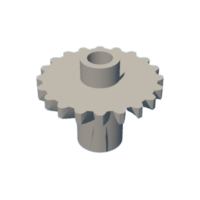
The other problem the gears will solve is the slight issue in the orientation of the spinning axis: the motor is horizontal, while the spinning axis of the turntable is vertical. To solve that issue, I placed two beveled gears right after the motor.
Step 7: Glueing the Big Gear in Place


Here comes the hardest part of this whole project: connecting the big gear in place.
The tolerances are very tight, and even a 1/32 inch variation can play a role in the final outcome of the project.
The big gear will need to be attached relative to the center of the spinning mechanism, not the plate in general! That means, that we can't just find the center of the plate, we need to focus on the mechanism:
First, remove the stand of the turntable. Mine had a hole through which I was able to access all the four screws that held the mechanism in place.
Then, draw two diagonal lines to find the center of the square formed by the four screw holes - that is the point we will be using to mount the big gear!
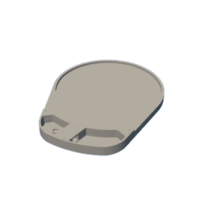
Using a compass, I was able to draw the outlines for the big gear, which I then glued in place with some superglue. If you wish, you can also add some screws for a more secure connection.
Step 8: Assembling Everything


Now that we have gone over all the components that make the project work, it's time to assemble everything!
Starting with the electronics:
I drilled the holes needed for the speed module knob and the DC power input and attached the corresponding components with the nuts they came with. I then soldered all the necessary wires in place.
Then, the motor enclosure:
The bigger beveled gear shaft has a hexagonal hole underneath, into which an M4 bolt can be pushed. Then, after putting the lid in place and placing the smaller flat gear on top, an M4 bolt can be inserted into the hole in the flat gear to tighten everything in place.
After that, the lid can be attached with some more M4 bolts.
Finally, the stand:
If you also made the stand separately out of dome MDF, glue the motor enclosure in place using some superglue. Then, you will be able to place the turntable on top and see whether it's at the right height. If not, add or remove material from the stand to make the two gears meet.
Once the height is right, find the perfect spot for the turntable to sit on. Place the small 3D printed circle around the bottom of the turntable and glue it in place.
And that's it! It's done! Remove the turntable and put it back on to check whether the gears click in place. If not, quickly stop celebrating and remove the 3D printed circle as the glue hasn't completely dried yet. You probably glued that circle a bit too far or too close to the motor. Glue it in place again, this time being more careful.
Voilà! Now it's done!
Step 9: Final Thoughts


I'm pretty happy with how my turntable turned out - although that's what like 99.98% of the makers say after finishing an exhaustive project.
The clicking mechanism is neat, it works just like I wanted it to! :)
However, the motor is a bit too weak, and when placing heavier items on the turntable it stops. So that's something to fix if you're going to attempt this project.
Also, for further improvements, a stepper motor would be a nice addition. Not only would it be quieter, but it would also allow for more precise motion during 3D scans.
Thank you for reading this far! I hope you liked my Instructable! :)
If you have any questions or comments, please leave them down in the comments below.
Stay creative, and have a wonderful day! :D

Participated in the
Electronics Contest


![Tim's Mechanical Spider Leg [LU9685-20CU]](https://content.instructables.com/FFB/5R4I/LVKZ6G6R/FFB5R4ILVKZ6G6R.png?auto=webp&crop=1.2%3A1&frame=1&width=306)


