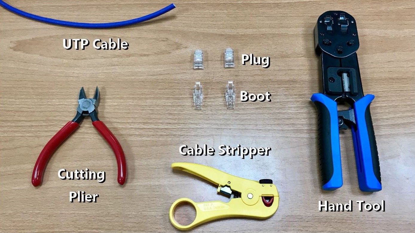
How to assembly an RJ45 Connector
A modular connector is a type of electrical connector for cords and cables of electronic devices and appliances, such in computer networking, telecommunication equipment. An 8P8C modular connection consists of a male plug and a female jack, each with eight equally-spaced contacts. On the plug, the contacts are flat metal bars positioned parallel to the connector body. Inside the jack, the contacts are metal spring wires arranged at an angle toward the insertion interface. The best known features of ANSI/TIA-568 are the pin/pair assignments for eight-conductor 100-ohm balanced twisted pair cabling. These assignments are named T568A and T568B.
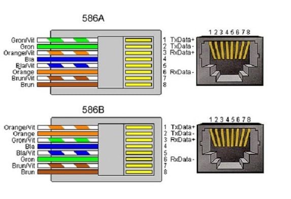
TIA-568A and TIA-568B Wiring Diagram
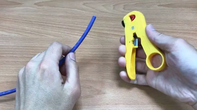
STEP 1, Use Crimping Tool to trim the cable.
Adjust the height of the knob before use to match the outer diameter of the LAN wire, and make sure the conducting wires are even.
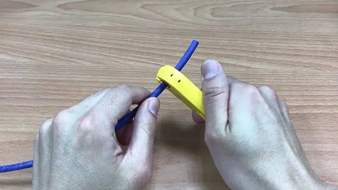
STEP 2, strip off approximately 3cm of the cable's jacket.
When stripping the outer jacket of the wire, be careful not to damage the inner conducting wires and prevent short circuits, you can also use a modular crimping tool or a cable stripper to strip it.
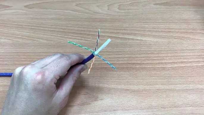
STEP 3, separate the 4 twisted wire pairs from each other.
Remove the cross and ripcord in the middle, if there is any. Unwind each pair, so that you end up with 8 individual wires.
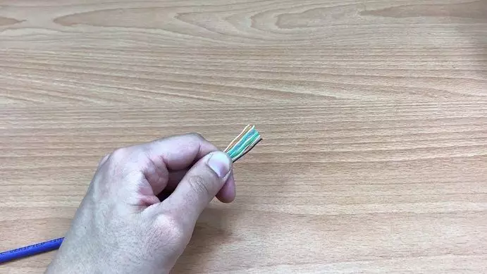
STEP 4, arrange the wires in a flat, side-by-side ribbon formation.
Holding the cable with the wire ends facing away from you. Moving from left to right. Remember, please check again to make sure the position is sorted according to the correct wiring map.
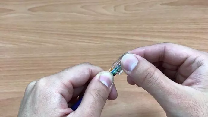
STEP 5, arranged wires into the connector.
Holding the RJ45 connector so that its pins are facing away from you and the plug-clip side is facing down, carefully insert the flattened, pushing through until the wire ends emerge from the pins. At this time, please push the wire forward as far as possible to reduce the length of the exposed twisted pair and achieve the best performance
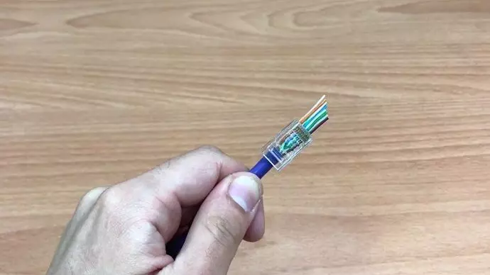
STEP 6, check to make sure that the wire ends coming out of the connector's pin side.
This is the last chance to check the wiring diagram before crimping the RJ45 plug. If you find an error, please take out the wire and re-arrange the wire again.
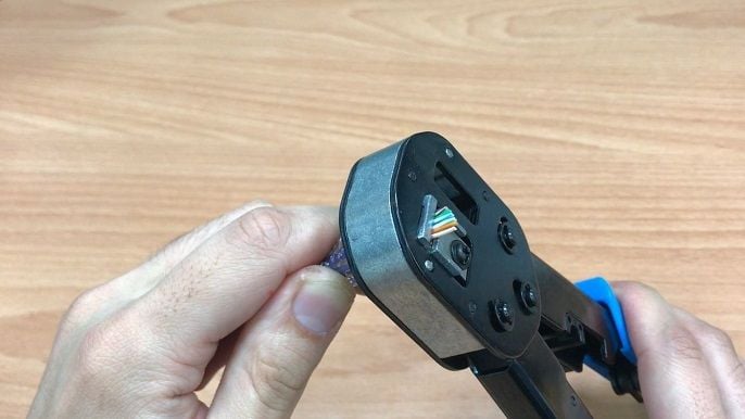
STEP 7, Insert the cable assembly into the RJ45 slot in the crimping tool.
Squeeze the crimper's handles together until you can't go any further. In these few simple steps, you can complete the assembly of RJ45 plug. In addition to being easy to assemble, it also has a good performance rate and is very suitable for use on the installation.
- Related Video
- Related Products
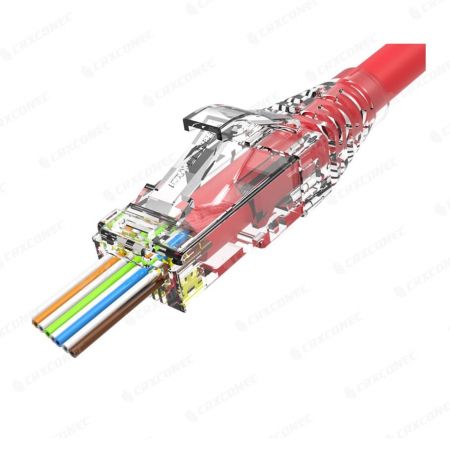
Cat6 UTP Easy Pass Through RJ45 Connector
PN.CC-01-00025
Easy Pass Through Series RJ45 Connector is specific for field installation, no need to take...
Details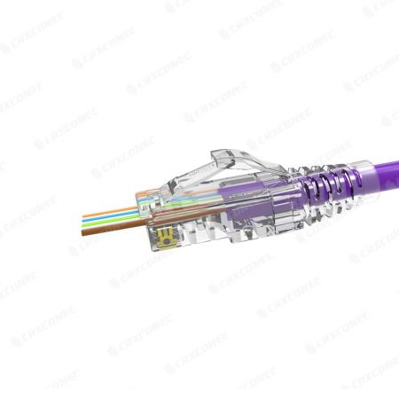
Cat5E UTP Easy Pass Through RJ45 Connector
PN.CC-01-00027
Cat.5E UTP Easy Pass Through RJ45 Plug can be used for 0.93~1.04 MM insulation and is suitable...
Details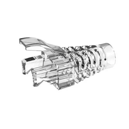
Modular Plug RJ45 boot
PN.CC-02-00129
The RJ45 Plug Boots are design to combine with UTP RJ connector or STP RJ modular plug more...
Details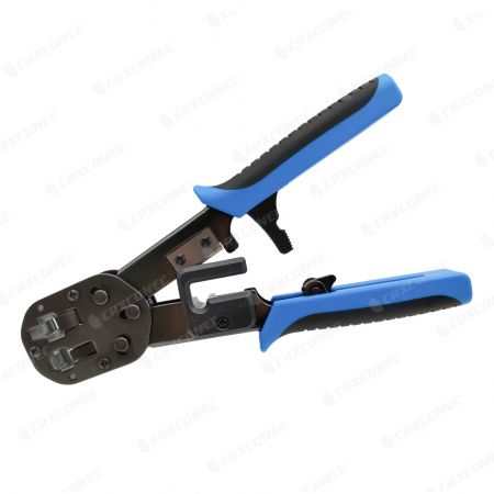
2-in-1 Easy RJ45 Plug Crimping Tool
PN.CC-15-00002
The Easy RJ45 Crimping Hand tool is not only designed for our Easy RJ45 plug but also the normal...
Details
Compact Ethernet Cable Stripper
PN.CC-15-00017
The Compact Ethernet Cable Stripper is suitable for multi-conductor cable, support jacket dimension...
Details- Files
CRX Share: Ready To Be A Pro Speedy Wiring Solution RJ45
Ready To Be A Pro Speedy Wiring Solution RJ45 Informative Share
DownloadCRX Share: What Is The RJ45 Connector Tested By?
An Overview To Test CRXCONEC RJ45 Connector
DownloadFAQ: 6 Things about RJ45 Connector Making, Testing, and OEM
CRXCONEC customers frequentl asked question about RJ45 connector.
Download