Introduction
Environmental pollution is the major problem of this world these days. Its causes different diseases in human beings. Flu, Silicosis, and Nausea are some of them. So, it is necessary to take action, and that’s why there is a dust sensor available to install at various places. It tells about the dust level and hence can be used at so many places. From hospitals to laboratories where we need high cleanliness, from construction field to transportation systems where measurement of dust is effective, and from food industries to open restaurants where neatness is crucial, this sensor can be used everywhere. But, how can we install them? You can interface the sensor with Arduino. How do you interface with them? This is what we are going to see in this article. So, in this tutorial, we are going to Make a “Dust Sensor Arduino Interface”
Working on Dust Sensor
The primary aspect of sensing dust is photometry. And, for this, it uses an IR emitter LED with a receiver photovoltaic diode (Photodiode). The sensor has an airflow path. Hence the IR LED and Photovoltaic are placed near that Airflow path. The pulse signal makes IR LED glow. When there are dust particles in Air it scatters and is received by the photodiode. Now the signal gets amplified and treated to get difference-level.
An Overview of Arduino
People often use the word microcontroller for the Arduino. But, that’s not correct. An Arduino is basically a simple electronic circuit board that makes the microcontroller easy to use. So what are the microcontrollers? Generally, the term microcontrollers are used for the integrated circuits (ICs) that are basically minicomputers, that can run small software programs, process, and runs the data faster than humans can imagine or think. In the past, we write the microcontrollers programs in binary coding, which also needs to understand the registers, etc. And, next special programming hardware having some custom-made cables was used to upload the programming to the microcontroller.
Hardware Required
| S.no | Component | Value | Qty |
|---|---|---|---|
| 1. | Arduino | UNO | 1 |
| 2. | USB Cable Type A to B | – | 1 |
| 3. | GP2Y1010AU0F | – | 1 |
| 4. | Capacitor | 47uf | 1 |
| 5. | Resistor | 100 ohm | 1 |
| 6. | Jumper Wires | – | 1 |
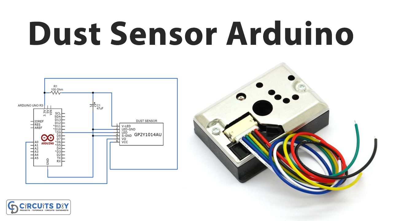
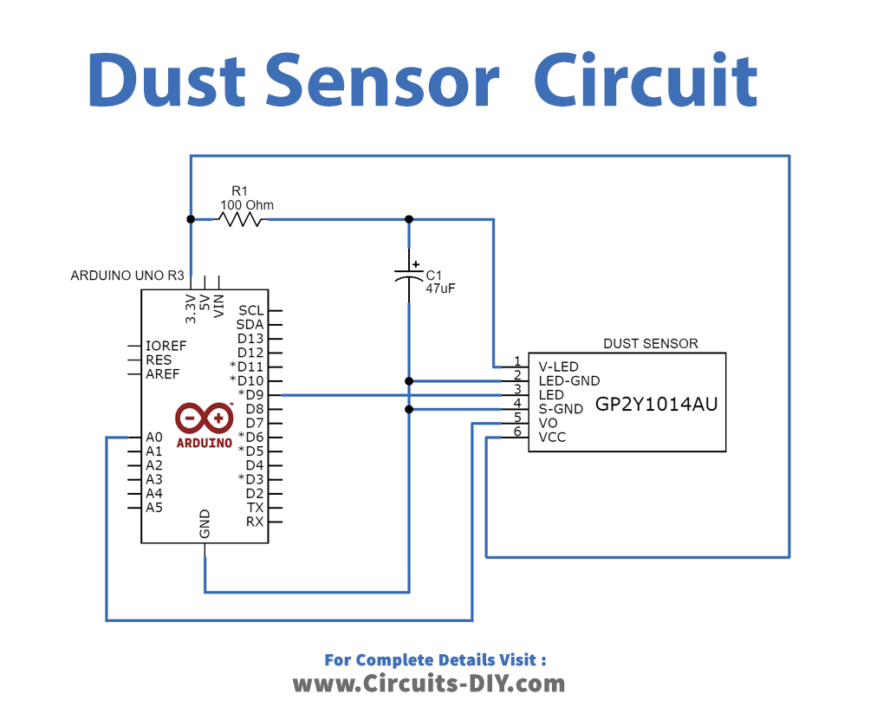
Circuit Diagram
Connection Table
| Arduino | GP2Y1010AU0F |
|---|---|
| GND | S-GND, LED GND |
| 3.3V | VCC, V-LED |
| A0 | VO |
| D9 | LED |
Arduino Code
int sensePin = A0;
int ledPin = 9;

int Tsampling = 280;
int Tdelta = 40;
int Tsleep = 9680;

float outVo = 0;
float sigVolt = 0;
float dustLevel = 0;

void setup(){
  Serial.begin(9600);
  pinMode(ledPin,OUTPUT);
}

void loop(){
  digitalWrite(ledPin,LOW);
  delayMicroseconds(Tsampling);

  outVo = analogRead(sensePin);

  delayMicroseconds(Tdelta);
  digitalWrite(ledPin,HIGH);
  delayMicroseconds(Tsleep);

  sigVolt = outVo * (3.3 / 1024);

  dustLevel = 0.17 * sigVolt - 0.1;

  Serial.print("Measured Signal Value (0-1023): ");
  Serial.print(outVo);

  Serial.print("   Voltage: ");
  Serial.print(sigVolt);

  Serial.print("   Dust Density Level: ");
  Serial.println(dustLevel);

  delay(1000);
}
Working Explanation
In this Dust Sensor Arduino Interface you need to connect the Arduino with them and for this follow the above-mentioned diagram. According to that, the 3.3V from Arduino board is provided to the Vcc pin and V-LED pins of dust sensor through 100 ohms Resistor. We connected the ground pin of the board to the LED-GND and S-GND pins of the sensor. We wired digital pin 9 with an LED pin and we declare it as an output pin. Vo pin of the sensor gives Analog output and therefore, is connected to the Arduino Analog input pin A0.
Code Explanation
- First, you need to define the sensor pins that are connected with the Arduino pins. Also, define some other accessory elements.
- In the void setup, define the sensor pin mode as the output.
- In a void loop, write the main program that includes some formulas and the needed output.
Application and Uses
- Hospitals, laboratories, industries, food sectors, weather stations, etc