 US
US
Gears
There are quite a few gear systems within LEGO, not all of which are compatible. This help page will go through each and give some information as well as spacing/ratio tips.
Instead of organising things chronologically, I have grouped items that have similar purpose and put lesser used systems near the end. The number in brackets is the teeth per stud of effective radius value for the gear system if known. The smaller the number, the larger the teeth on the gear.
In 1977 LEGO released the gear tooth system that is still in use today. They started off with 8, 24 and 40 tooth gears but quickly added a 16 tooth version in 1979. This gear system is also compatible with technic links, which were released in 1978.


In 1999 the double bevel gears were introduced, with a new range of teeth numbers to choose from. They started out with 12 and 20, but added 36 a few years later in 2002, and a 28 much later in 2019. The double bevel shape of the teeth means the same part can be used to connect gears linearly, as well as at right angles, however it loses compatibility with the technic links. The 12 and 20 tooth gears recently saw the release of non-beveled versions in 2022.


While the teeth still mesh ok with the previously released gears, getting the spacing right between the two gear families is challenging. The first batch of gear sizes 40, 24, 16 and 8 I wall call group A, and the second set of sizes 36, 28, 20 and 12 I will call group B. The B group didn't replace group A, both sets are still in production today.
These 8 gears are commonly considered as the set of standard LEGO gears, other sizes do exist, but for more specialised usages. Sariel's gear ratio calculator has a good visual overview of different gears available for each number of teeth, but does seem to be missing some of the newer gears.
Gear Ratios
Combining gears of different sizes will affect the speed in which they turn, as well as the force needed to turn something. For example, say you join a 8 tooth and a 40 tooth gear, this has a gear ratio of 8:40 or 1:5 or 0.2:1. The ratio stays the same when you multiply both sides by the same number. It can also be expressed as a single number, which is the number when one of the sides is 1. In this case the gear ratio is 5 or 0.2 depending on which gear is being driven. This ratio means turning the 40 tooth gear once will see the 8 tooth gear rotate 5 times. Or if you turn the 8 tooth gear once, the 40 tooth gear will complete 0.2 of a rotation.

If you are using a motor that runs at a fixed speed you can use gear ratios to speed things up and slow things down, but remember it will also affect the force needed. Like when you are riding a bike, changing to a lower gear makes the pedals easier to push when going up hill, but you will also go more slowly. If a motor is struggling to move something, changing the gear ratio to make things slower will help.
If you have multiple gears stacked in a line, the intermediate gears will not affect the gear ratio, only the first and last gears matter. For example say you have an 8 gear then a 40, then another 8. You have a gear ratio of 8:40 and 40:8. Combined this becomes 8*40:40*8 the numbers on each side cancel out leaving us with 1:1. Each turn of the 8 tooth gear on the left will result in a full turn of the 8 tooth gear on the right.

However when gears are stacked on an axel, then the combined ratio must be determined. If you have a 8:40 stacked with another 8:40 as in the below image, you then end up with a 8*8:40*40 which works out to be 1:25. The left axel will need to be turned 25 times before the right axel completes one rotation. Turning the right axel once will see the left one zip around 25 times.

The below table shows all gear ratios of the currently available standard gears. Of special note is the worm gear, it is considered to have 1 tooth for ratio calculations as a full rotation of the worm gear will only advance the connected gear by 1 tooth. This is because there is a single ridge that spirals around the gear.
Table 1: Gear Ratios
| 40 | 36 | 28 | 24 | 20 | 16 | 12 | 8 | 1 | |
| 40 | 1.00 | 1.11 | 1.43 | 1.67 | 2.00 | 2.50 | 3.33 | 5.00 | 40.00 |
| 36 | 0.90 | 1.00 | 1.29 | 1.50 | 1.80 | 2.25 | 3.00 | 4.50 | 36.00 |
| 28 | 0.70 | 0.78 | 1.00 | 1.17 | 1.40 | 1.75 | 2.33 | 3.50 | 28.00 |
| 24 | 0.60 | 0.67 | 0.86 | 1.00 | 1.20 | 1.50 | 2.00 | 3.00 | 24.00 |
| 20 | 0.50 | 0.56 | 0.71 | 0.83 | 1.00 | 1.25 | 1.67 | 2.50 | 20.00 |
| 16 | 0.40 | 0.44 | 0.57 | 0.67 | 0.80 | 1.00 | 1.33 | 2.00 | 16.00 |
| 12 | 0.30 | 0.33 | 0.43 | 0.50 | 0.60 | 0.75 | 1.00 | 1.50 | 12.00 |
| 8 | 0.20 | 0.22 | 0.29 | 0.33 | 0.40 | 0.50 | 0.67 | 1.00 | 8.00 |
| 1 | 0.03 | 0.03 | 0.04 | 0.04 | 0.05 | 0.06 | 0.08 | 0.13 | 1.00 |
Sariel's gear ratio calculator is a great tool if you want to combine gears in a more complex ways.
Linear Spacing
In order to have the gears spinning smoothly, you need to have the right spacing between each. In order to determine different spacing arrangements, I first measured what I am calling the effective radius of each gear. The actual radius would be the tip of the tooth to the centre of the gear, but gears need to overlap slightly, so this measurement isn't particularly useful. To determine the effective radius I took two of the same gear and placed them on a technic beam in such a way that the teeth meshed smoothly. Then I measured the distance between the centre of each and divided by 2.
To determine the ideal spacing of any two gears, you simply add the effective radius of each.
Table 2: Effective Radius
| Teeth | Effective radius (studs) | Group |
| 40 | 2.5 | A |
| 36 | 2.25 | B |
| 28 | 1.75 | B |
| 24 | 1.5 | A |
| 20 | 1.25 | B |
| 16 | 1 | A |
| 12 | 0.75 | B |
| 8 | 0.5 | A |
Of note, all gears in the above table have exactly 16 teeth per stud of effective radius. This is why they mesh well together, the teeth have the same spacing at the pinch point. The B group gears all increment by 0.5 studs each time, however group A has a gap. In the future LEGO may choose to release a 32 tooth gear with effective radius of 2 studs, but for now it is just an awkward gap which makes some of these tables slightly less pretty.
As you can see, gears from group A all ended with either .0 or .5 studs radius, while group B ended with .25 or .75 studs radius. The below table I have calculated the ideal spacing between each combination of these 8 standard gears which shows the compatibility problem. When combining two gears from the same group the ideal spacing ends in .0 or .5, but when combining gears from opposing groups you are left with an ideal spacing ending in 0.25 or 0.75.
Those ending in .0 can be placed adjacent on a technic beam and will be shaded green in the following tables. Those ending in .5 need ahalf stud offset for one of the gears to make the spacing work, such as part 6541 and will be shaded orange. Those ending in 0.25 and 0.75 have no easy way of being meshed on a standard technic beam and will be shaded red.
Table 3: Ideal Spacing
| 40 | 24 | 16 | 8 | 36 | 28 | 20 | 12 | |
| 40 | 5 | 4 | 3.5 | 3 | 4.75 | 4.25 | 3.75 | 3.25 |
| 24 | 4 | 3 | 2.5 | 2 | 3.75 | 3.25 | 2.75 | 2.25 |
| 16 | 3.5 | 2.5 | 2 | 1.5 | 3.25 | 2.75 | 2.25 | 1.75 |
| 8 | 3 | 2 | 1.5 | 1 | 2.75 | 2.25 | 1.75 | 1.25 |
| 36 | 4.75 | 3.75 | 3.25 | 2.75 | 4.5 | 4 | 3.5 | 3 |
| 28 | 4.25 | 3.25 | 2.75 | 2.25 | 4 | 3.5 | 3 | 2.5 |
| 20 | 3.75 | 2.75 | 2.25 | 1.75 | 3.5 | 3 | 2.5 | 2 |
| 12 | 3.25 | 2.25 | 1.75 | 1.25 | 3 | 2.5 | 2 | 1.5 |
For beginners, I would stick with combing gears from either the A or B groups, and not trying to mesh gears from opposing groups. However it must be possible right? If you can't do it on a straight beam, what about up at an angle? If you make a wall out of technic bricks you can get some interesting spacings, especially when you throw plates and on stud holes into the mix. To help find solutions for our unusual gear spacings I used good old Pythagoras theorem to calculate the distance in studs for all possible spacings for a technic brick wall. I have highlighted cells below that work for one or more gear combos, noting that spacings for these are not always ideal, gears may be tighter or looser than normal.
Table 4: Brick Grid Spacing
| 0B | 0.000 | 0.500 | 1.000 | 1.500 | 2.000 | 2.500 | 3.000 | 3.500 | 4.000 | 4.500 | 5.000 |
| 1P | 0.400 | 0.640 | 1.077 | 1.552 | 2.040 | 2.532 | 3.027 | 3.523 | 4.020 | 4.518 | 5.016 |
| 2P | 0.800 | 0.943 | 1.281 | 1.700 | 2.154 | 2.625 | 3.105 | 3.590 | 4.079 | 4.571 | 5.064 |
| 1B | 1.200 | 1.300 | 1.562 | 1.921 | 2.332 | 2.773 | 3.231 | 3.700 | 4.176 | 4.657 | 5.142 |
| 1B+1P | 1.600 | 1.676 | 1.887 | 2.193 | 2.561 | 2.968 | 3.400 | 3.848 | 4.308 | 4.776 | 5.250 |
| 1B+2P | 2.000 | 2.062 | 2.236 | 2.500 | 2.828 | 3.202 | 3.606 | 4.031 | 4.472 | 4.924 | 5.385 |
| 2B | 2.400 | 2.452 | 2.600 | 2.830 | 3.124 | 3.466 | 3.842 | 4.244 | 4.665 | 5.100 | 5.546 |
| 2B+1P | 2.800 | 2.844 | 2.973 | 3.176 | 3.441 | 3.754 | 4.104 | 4.482 | 4.883 | 5.300 | 5.731 |
| 2B+2P | 3.200 | 3.239 | 3.353 | 3.534 | 3.774 | 4.061 | 4.386 | 4.742 | 5.122 | 5.522 | 5.936 |
| 3B | 3.600 | 3.635 | 3.736 | 3.900 | 4.118 | 4.383 | 4.686 | 5.021 | 5.381 | 5.763 | 6.161 |
| 3B+1P | 4.000 | 4.031 | 4.123 | 4.272 | 4.472 | 4.717 | 5.000 | 5.315 | 5.657 | 6.021 | 6.403 |
| 3B+2P | 4.400 | 4.428 | 4.512 | 4.649 | 4.833 | 5.061 | 5.325 | 5.622 | 5.946 | 6.294 | 6.660 |
| 4B | 4.800 | 4.826 | 4.903 | 5.029 | 5.200 | 5.412 | 5.660 | 5.941 | 6.248 | 6.580 | 6.931 |
For example, say you are looking to combine a 36 and 24 gear, this has an ideal spacing of 3.75 studs. In the above table we look for numbers that are close to 3.75 and shaded in red (as the spacing is ending in either 0.25 or 0.75). 1 stud, 3 bricks is close at 3.736, or we could use 2.5 studs, 2 bricks and 1 plate which is 3.754. The closer we get to the ideal spacing, the smoother the gears will mesh, if the number starts getting too large it will be a bit loose. Below you can see these two combinations demonstrated.


If we want to mesh an 8 and a 12, we are looking for a 1.25 spacing, the closest is 1 brick and 2 plates. This one is a bit tricky and needs on stud bricks despite the full stud spacing. There are a couple of bolded numbers in the table above, these spacings worked ok for larger gears, but combinations using the 8 tooth gear were prone to slipping. This means there is no way to directly mesh an 8 and 20 tooth gear using a brick grid. All other gear combinations are possible.

However, a lot of technic sets do not contain many technic bricks, but instead use smooth lift arms to create a regular grid with uniform stud spacings on both axis. This scenario is a bit more limited than the brick grids. There is still a decent amount of combinations with all gears able to be meshed via an intermediate gear. This video gives a great run down on placement options for a regular grid.
I have also made a table with the same formatting to show where the possible green, yellow and red combinations are. You will notice this table is symmetrical along the diagonal axis.
Table 5: Regular Grid Spacing (studs)
| 0 | 1 | 2 | 3 | 4 | 5 |
| 1 | 1.414 | 2.236 | 3.162 | 4.123 | 5.099 |
| 2 | 2.236 | 2.828 | 3.606 | 4.472 | 5.385 |
| 3 | 3.162 | 3.606 | 4.243 | 5.000 | 5.831 |
| 4 | 4.123 | 4.472 | 5.000 | 5.657 | 6.403 |
| 5 | 5.099 | 5.385 | 5.831 | 6.403 | 7.071 |
There are also certain combination of technic parts that allow half stud offsets. You will need to get a bit creative to create specific spacings, but here a few examples of part combinations which give half stud offsets which might be used as a starting point. These can be used in conjunction with other thechnic beams and panels to create even more spacing options.


This means the above table can be expanded to include half stud spacings. I have listed this as a seperate table, as I think some people may prefer to stick with the simpler full stud spacing only. This does open up quite a few more combinations that no longer need an intermediate gear. We are still missing 1.25 and 3.25 stud spacing options, but the rest are present.
Table 6: Regular Grid Spacing (half studs)
| 0 | 0.5 | 1 | 1.5 | 2 | 2.5 | 3 | 3.5 | 4 | 4.5 | 5 |
| 0.5 | 0.707 | 1.118 | 1.581 | 2.062 | 2.550 | 3.041 | 3.536 | 4.031 | 4.528 | 5.025 |
| 1 | 1.118 | 1.414 | 1.803 | 2.236 | 2.693 | 3.162 | 3.640 | 4.123 | 4.610 | 5.099 |
| 1.5 | 1.581 | 1.803 | 2.121 | 2.500 | 2.915 | 3.354 | 3.808 | 4.272 | 4.743 | 5.220 |
| 2 | 2.062 | 2.236 | 2.500 | 2.828 | 3.202 | 3.606 | 4.031 | 4.472 | 4.924 | 5.385 |
| 2.5 | 2.550 | 2.693 | 2.915 | 3.202 | 3.536 | 3.905 | 4.301 | 4.717 | 5.148 | 5.590 |
| 3 | 3.041 | 3.162 | 3.354 | 3.606 | 3.905 | 4.243 | 4.610 | 5.000 | 5.408 | 5.831 |
| 3.5 | 3.536 | 3.640 | 3.808 | 4.031 | 4.301 | 4.610 | 4.950 | 5.315 | 5.701 | 6.103 |
| 4 | 4.031 | 4.123 | 4.272 | 4.472 | 4.717 | 5.000 | 5.315 | 5.657 | 6.021 | 6.403 |
| 4.5 | 4.528 | 4.610 | 4.743 | 4.924 | 5.148 | 5.408 | 5.701 | 6.021 | 6.364 | 6.727 |
| 5 | 5.025 | 5.099 | 5.220 | 5.385 | 5.590 | 5.831 | 6.103 | 6.403 | 6.727 | 7.071 |
Please note those with half stud offsets have not been confirmed with physical bricks. Shading is filled in based on observed tollerances in other tested scenarios. Please let me know on the forums if you find any errors!
Right Angle Spacing
Ok, now we can confidently place gears on a single plane, what about corners? The obvious solution is bevel gears. All gears in group B come in a double bevel format as standard. This allows them to be easily placed for both internal and external corners. We also have half width bevel gears to choose from and the 24 tooth crown gear which allows A group gears to be used at right angles.


For each of these the thickness of the gear becomes important. Say you are meshing gears X and Y around a corner. To figure out the spacing of gear X to the corner, add the effective radius of gear X to the thickness of gear Y using the table below.
Table 7: Corner Thickness
| Gear Type | Inside Corner Thickness | Outside Corner Thickness | Meshes With |
| double bevel | +0.75 | -0.25 | bevels |
| half bevel pin | +0.25 | -0.75 | bevels |
| half bevel | +0.25 | -0.25 | bevels |
| 24 tooth crown | +0.5 | -0.5 | regular gear |
| regular gear | +0.5 | -0.5 | crown |
For example, when using double bevel gears on an internal corner you need an additional 0.75 studs on top of the effective radius to the edge of the inside corner. The 20 tooth gear pictured below has an effective radius of 1.25 studs, so requires a spacing of 2 studs between the edge of the corner and centre of the axel hole. For external corners the gear needs to protrude 0.25 suds over the edge, so the 20 tooth gear needs to be spaced with the centre 1 stud from the corner.


This means the 20 and 36 tooth gears are easier to mesh on corners built with bricks, as their effective radius both end in .25, so adding 0.75 thickness leaves you with a whole number of studs making spacing simple. If you want to use 12 or 28 tooth gears around a brick corner, you can either use on stud bricks, or you can combine them with a half bevel gear to reduce the gap needed to 0.25 studs. The 12 tooth gear below has an effective radius of 0.75 studs, so requires 1 stud spacing to the inside of the corner when paired with a half bevel. The 28 tooth gear also works nicely on a technic frame, which has different hole spacing to a brick built corner.
If used on an external corner the pin version of the 20 tooth half bevel gear increases the required overhang to 0.75 studs, which makes the 12 tooth gear too small to be used. It can be combined with a 28 tooth gear on an outer corner, but one of the gears needs to be mounted on the other side as the joining hole for each would clash. The half width bevel gears maintain the same external corner thickness as double bevel gears.


The 24 tooth technic crown gear had a few variants spanning from 1977 to 2013 and is unique in its ability to join with regular flat toothed gears at a 90deg angle. Its thickness of 0.5 studs makes it mesh well with group A gears. It is also able to mesh linearly with straight toothed gears with the same spacing as the regular 24 tooth gear.


Worm Gear
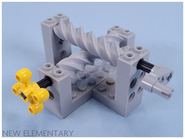
Worm gears also use a type of right angle connection, however unlike the scenarios above the two axis of rotation do not intersect. The effective radius of the original worm gear is 0.5 studs, placing it in group A. This is the same as an 8 tooth gear, but the axel needs to be vertical through this point. It can be a bit challenging, especially for beginners, to create a brick built structure to place a worm gear adjacent to a regular gear. The structures created below are to demonstrate the spacing, and not strong enough for practical use.


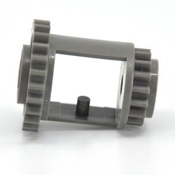
Thankfully LEGO has also released some gearboxes to address this issue, 6588 allows you to easily combine a worm gear with a 24 tooth gear. There is also a version 46224c01 which has the gears permanently built in. The main disadvantage of these gearboxes is they only work with the 24 tooth gear. For other sizes you still need to get creative.
You might have noticed that the worm gear isn't quite 2 studs long. It has a bit of wiggle if placed in a 2 stud gap. Why is this? The rest of the gears in this system have a tooth spacing of 16 teeth per stud of effective radius. This can also be expressed as 2.546 teeth per stud of circumference (C = 2 Pi r). The worm gear has 5 teeth along the shaft, so if this is to have the exact same spacing as the other gears, the length of the shaft will need to be 1.96 studs long. LEGO could have continued the spiral around a bit further to complete the 2 stud length, but then the tooth wouldn't line up if trying to join multiple worm gears. They also could have stretched out the spacing, but then the teeth wouldn't mesh as neatly, so we are left with this odd size. For a worm gear that won't slide around there is always 15457 Technic Worm Gear 3L with Bush Ends.
Double bevel teeth will turn from a worm gear, but they don't fit as well, possibly due to the width of the teeth. It is recommended to use the original worm gear with regular straight teeth gears. If you want to use a worm gear with bevel gears, part 27938 is the answer. The teeth on this one are wider, making the effective radius 0.75 studs. This is the group B worm gear.


Another thing to note with these worm gears is they are unidirectional. The normal gear can be powered by the worm gear, but if you try to turn the normal gear, the worm gear won't budge. This can be useful when positioning something heavy, as the weight won't cause the gears to slip backwards.
Other Technic Gears
Rack Gears
There are quite a few options for rack gears, which are a great way to change rotational movement into linear movement. Above I mentioned that the modern gear system uses a tooth spacing of 2.546 teeth per stud of circumference. Rack gears don't have a radius so we need to use the circumference value to compare spacing. 3743 is 4 studs long and has 10 teeth, making the ratio 2.5 teeth per stud. Not a perfect match, but close enough for things to move smoothly. This is equivalent to 15.71 teeth per stud of radius.


New Worm Gear
In 2023 LEGO released a new worm gear variant, Technic Worm Gear 6M with Axle Hole. This is very different from the original worm gear. First of all, there are 4 teeth that circle around the gear instead of 1, so you need to treat it as a 4 tooth gear for ratio calculations. Along the linear length of 6 studs, you can count 6 ridges which gives it a tooth spacing of 1 tooth per stud of circumference, or to make it easier to compare to the other systems, 6.28 teeth per stud of radius. This doesn't match with any other gear system, the only easily compatible parts are the specially made brick casings, as well as the ability to mesh with itself at a right angle with 1 stud offest.


TobyMac did a blog for New Elementary and did find some ways to mesh regular gears if mounted at 45deg angle. Changing the angle, changes the spacing of the teeth, but it still needed at least 2 regular teeth to one worm gear tooth. It would be much simpler to just add a regular gear to the same axel if you want to combine the systems.
14, 22 Tooth and Differentials
Differentials are a type of gear housing that contains 3 inner gears at right angles and is often used when building vehicles to allow two opposing wheels to turn at different speeds. When cars turn corners, the inner wheel travels a shorter distance than the outer wheel, differentials allow this to occur.
The first differential was released back in 1980 along with group A gears but does not mesh with them due to how far it sticks our from the technic beam. It strangely has 28 teeth and is designed to be used with the older 14 tooth half bevel, with three of the 14 tooth gears placed inside, and a fourth used to power the 28 tooth outer gear.

The 14 tooth gear can also be used without the differential to create a tight 90deg angle change, which was useful as there were not many beveled options for gears initially. Linearly, you can sort of mesh it with itself by putting one on the axel backwards, but it needs some finnicky axel alignment, and I wouldn't recommend this arrangement. More usefully, it can mesh with group B bevel gears in the same spacing as a 12 tooth gear. Being able to substitute a 14 tooth could be helpful if you are aiming for a highly specific gear ratio.


In 1994 they updated the differential to have a standard 24 tooth and 16 tooth gear at each end. This means it meshes well with group A gears. From now on differentials have all used the more modern 12 tooth thin bevel gear for the internal gears. This version had a fair bit of overlap with the next, as it stayed in production until 2021. The third iteration was released in 2008 and has had a few different mold variants. It is back to using a 28 tooth outer gear, but instead of the weirdly offset crown, it is a standard half width bevel. This version meshes well with group B bevel gears.


More recently in 2020 LEGO released a differential with a bit more assembly required. This one allows you to add either a 22 tooth half bevel, or a 28 tooth double bevel to the top. Another difference is instead of having a single bevel gear to transfer between the two axels, this casing contains three. My guess is it makes for a sturdier, and more balanced part.


To go with the latest differential LEGO recently released a 22 tooth and new 14 tooth bevel gears. There have a different tooth spacing and thicknesses to the standard gear system. They mesh nicely with each other at a right angle, but I haven't found any other clean matches.
Clutch Gears
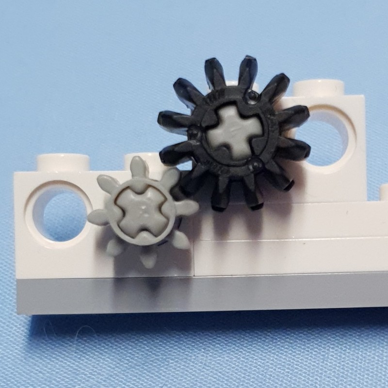
If you see the word clutch in a gear name it could mean a couple of different things. The one I am most familiar with is the old 24 tooth white clutch which had two mold variants spanning from 1997 - 2018. This gear the inner axel can move separately from the outer teeth if enough force is applied. It was a good way to protect old motors, if they weren't strong enough to move the thing, the inner axel would start to slip.

Most of the other clutch gears refer to gears that can be engaged and disengaged on an axel by a part that locks into the side. The first attempt at this was all the way back in 1993 with this 16 tooth gear.


This actually has two clutching mechanisms, one on each side. The fine toothed ridges can pair with specialised half bushes and a few other parts, mostly technic plates. The other side has 4 ridges which is the mechanism that has stuck around. There are so far 3 different types of technic driving rings using this 4 ridge interlocking system. The most recent variant has 8 ridges instead of 4, this is still compatible with any of the 4 ridge parts, but just means every other tooth will be used, and there will be a smaller amount of free rotation before the gear engages.


There are also 2 extension pieces, one with 4 ridges and a newer one with 8, which will allow you to increase the length of any of the above parts. The currently available gears that can use this gear selection mechanism is 16, 20 (both with and without bevel) and 24. More may be added in future.


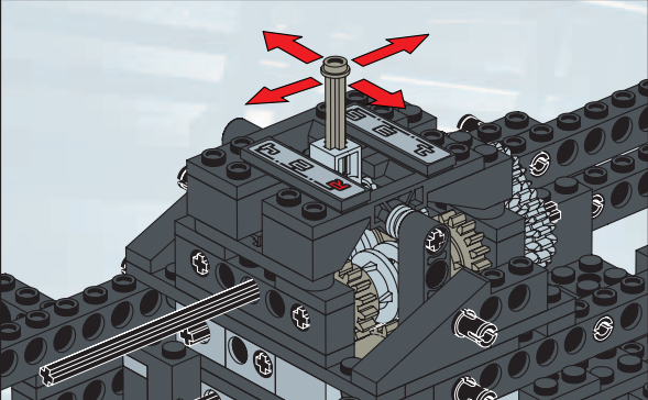
The first switching system uses 6539 as the driving ring which is moved by part 6641/51149 on a lever often guided by part 6631 Technic Changeover Plate. See below instruction snippet from set 8466-1 - 4x4 Off Roader.
Simon goes over the second switching system in his review of the Bugatti Chiron. This uses part 18947 as the driving ring and the orange part 35188 to select the gears. Below is one of the images from the review, check out the full review for more.

TobyMac gives a good run down of the third switching system inside this set review of the Yamaha MT-10 SP. This system uses part 2473 as the driving ring, along with the medium azure 4158 Gear Shifter with Groove, and orange 4159 Gear Shifter Fork to control the movement. I have included one image below, but check out the review for more images, gifs and videos exploring the mechanism further.

8 Tooth Gear Stepper / Timing Wheel
This third system also introduces the yellow 2474 Technic Gear Stepper with 8 Tooth. While it looks like a gear, its main purpose is not to mesh with other gears, but to allow positions of exactly 1/8th of a rotation. This is required in order to get the medium azure drum into the correct locations to engage the driving ring.
It can also be used as a gear with an effective radius of 1 stud (8 teeth per stud of effective radius), however there will be some slack due to the shape of the teeth and it won't mesh with other gear systems. As it is not designed for this, there could even be risk of damaging the part if you apply too much force.
New Elementary goes over the geometry in more detail in their review of the set.
There is another 8 toothed gear that is not really a gear, this is the old Timing Wheel that had one usage in white in 1997 then wasn't seen again until 2000. The white gear was used to measure drive train speed by the code pilot in set 8479-1 - Barcode Multi-Set. From 2000 onwards it is only available in light grey or later light bluish grey. While it can sort of be placed next to itself on a beam, it will not turn. It can be used to interlock with the caterpillar tred wheel hub part 32007, but a 16 tooth gear will do a much neater job.


From 2000 onwards it is mostly used aesthetically, including multiple Exo Force sets where you insert a bunch of binoculars. It is used as what seems to be a latch to pause the output of a wind up motor in set 3429-1 - Ultimate Defense as seen above.
Turntables
Turntables are some of the largest single part gears we have in modern gear systems. These have seen some changes over the years, with older variants having 56 teeth, and newer ones having 60. While they have an opening instead of a central axel hole, you can create a centre hole with the addition of technic plates, beams, or other parts. In this way I was able to measure the effective radius of each.
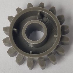
The old 56 tooth turntable has an effective radius of 3.5 studs, which places it in group A, able to do regular spacings on a standard technic beam with other group A gears. The hole in the middle will snugly fit a 24 tooth gear.


The 60 tooth turntable has an effective radius of 3.75 placing it in group B. This makes it easier to line up with other B group gears.


There is also a smaller 28 tooth turntable which is the same size as a regular 28 tooth gear, however it has straight teeth instead of beveled ones.
Treads / Links / Chain
In 2007 LEGO released a different link system, mostly used as treds for vehicles. This requires a different type of gear to turn smoothly, and comes with teeth options of 6, 10 and 14. The shape of the teeth means these gears are unable to mesh with each other, and can only mesh with the chain links. As it uses a chain system to link gears, the spacing is less critical with some slack still allowing things to move smoothly.


Because we don't need nice uniform gear radii to line up the gears with each other, the spacing for this system gets a bit strange, and I had to measure their radii in a different way. Two technic links will span 3 studs exactly when held taught. Using trigonometry to draw triangles between the link notches and centre of the gear we can calculate effective radii of 1.5, 2.43 and 3.37 studs (rounded to 2 decimal places).
This also lets us calculate the tooth spacing ratio, however each gear gives a slightly different result. Starting with the smallest gear we get 4.00, 4.12 and 4.15 teeth per stud of effective radius. So why are they different? These gears only mesh with the chain links, not other gears, so it is important that the straight line between two notches is kept uniform. While circumference has a linear relationship to radius, this straight line segment does not.
This spacing is very close to the splat gear system, but not close enough for splat gears to work smoothly with the links.
Knob Gear and Plates / Splat Gears
Knob Gear
The 4 toothed nobly gear has been around since 1998 and is commonly used in sets as a handle. It can also be used as a gear, and was initially only compatible with itself. It has a effective radius of 1 stud, and can be used both linearly and at right angles with on stud holes. It has 4 teeth per stud of effective radius making the teeth 4 times larger than those on the modern gear system.

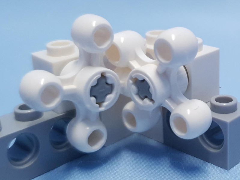
This gear had a recent update in 2024. 5405 Technic Knob Wheel 45° Offset (in Light Bluish Grey) is a variation of 32072 Technic Knob Wheel (in Black), with the main difference being the axle hole, which is rotated 45 degrees. This allows for 2 knob gears to be lined up next to each other with the connecting axles in the same orientation, as shown in the photo. Depending on the need, this makes certain functions possible that weren't before.


This gear has minimal backlash, meaning when you change direction there isn't much wiggle room. This makes it ideal for the drivetrain for steering, as a change in direction will be immediately passed on.
Plate / Splat Gears
In 2019 LEGO released gears that didn't form part of the technic system. These gears are specially shaped plates and come in 6, 10 and 14 tooth options. They have an effective radius of 1.5, 2.5 and 3.5 studs respectively. This gear system uses 4 teeth per stud of effective radius.


As the studs on top of the gear align differently to each tooth, it is often important to make sure the gear is in the correct orientation when you place it. Keep an eye on the placement arrow which is indented on a single tooth, and often referenced by instructions.

Plate gears have the same tooth spacing as the technic knob gear, and both use a rounded tooth shape. This means they are compatible with each other when used linearly, however they did not work smoothly when joined at 90deg.
Vintage
Samsonite Gears
LEGOs first attempt at gears was all the way back in 1965 with these 4 samsonite gears that came in 14, 21, 35, and 42 teeth variants. These gears ended production in 1969 or 1971 depending on the gear. They have an effective radius of 2, 3, 5 and 6 studs respectively which makes the tooth spacing of this system 7 teeth per stud of effective radius.


Large Tooth Gears
In 1970 LEGO started production of large tooth gears which came in 9, 15 and 21 tooth variants. Two of these only lasted until 1974 with the 9 tooth gear hanging around until 1977 as it was being used as a wheel hub. This was also LEGOs first attempt at chain with 273 being compatible with these gears. They have an effective radius of 1.5, 2.5, and 3.5 studs respectively, which makes the tooth spacing for this system 6 teeth per stud of effective radius.


While the teeth look to be a similar shape to the samsonite gears, as the tooth spacing ratio is different they are not compatible with the samsonite gears.
Duplo
Duplo has not one but two gear systems.
Duplo Technic
Duplo Technic mirrors the gear selection of A group LEGO gears offering an 8, 24 and 40 tooth option, only at a larger scale. The 24 tooth gear comes in a crown variant also matching the LEGO offering. The 8 tooth gear only comes as part of an axel, but there are a couple of lengths to choose from. They have an effective radius of 1, 3 and 5 LEGO studs respectively, making the tooth spacing 8 teeth per stud of radius, or exactly twice as large as the LEGO equivalent system, which makes sense with Duplo studs being twice as big.


There is also a worm gear with specialised holder that forms part of this system.
Duplo Plate / Splat
Duplo also has a version of plate / splat gears. These come in two sizes, 8 and 12 teeth, with effective radius of 4 and 6 LEGO studs respectively. This means the Duplo splat gears have a tooth spacing of 2 teeth per stud of effective radius.

